D.C. Circuits
In this article we will learn about D.C. Circuits. We will get to know
- The basic ideas of what constitutes a series circuit and a parallel circuit.
- Current is equal at all points along a series circuit and e.m.f. = sum of p.d. across all components.
- Current in main path = sum of the current in all parallel paths, and p.d. across all parallel paths are equal.
The details covered in the article are as per the requirements of the Secondary 4 Physics class.
Introduction To D.C. Circuits
The D.C. in D.C. circuits stands for Direct Current. For D.C., current only flows in one direction, i.e. from the positive terminal to the negative terminal of the power source.
The opposite of D.C. current is A.C. current and it stands for Alternating Current.
Electromotive Force(e.m.f.)
Before directly diving into the circuits, let us be clear about a concept called electromotive force.
- Identical Cells In Series
When identical cells are arranged in series, the resultant e.m.f. is the sum of all the e.m.f.s of the cells.

In the above image, both cells, each of 1.5 V, are arranged in series. The resultant e.m.f. is the sum of the e.m.f. of the two cells which is 3.0 V (\(=1.5+1.5\)).
- Identical Cells In Parallel
When identical cells are arranged in parallel, the resultant e.m.f. Is equal to that of a single cell.

In the above image, both cells, each of 1.5 V, are arranged in parallel. The resultant e.m.f. will be the e.m.f. of a single cell, which is 1.5 V.
Question 1:
Match the correct description to the correct circuit diagram.

- Series , Parallel
- Parallel , Series
Solution:
In the first setup, the main circuit path from the cell will eventually split into two different paths before rejoining to a single path back to the cell. This is a parallel circuit.
In the second setup, there is only a single path for the current to flow through. This is a series circuit.
The correct answer is (B)
Series vs Parallel Circuits
| Series Circuits | Parallel Circuits |
|---|---|
|
|
|
|
|
|
|
|
|
|


Question 2:
What is the relationship between the 2 currents (with respective ammeter readings) in the circuit below?

- \(I_1
- \(I_1=I_2\)
- \(I_1>I_2\)
Solution:
The setup has only one path through which the current flows. Therefore, their values will be the same.
The correct answer is (B).
Question 3:
What is the relationship between the 2 currents (with respective ammeter readings) in the circuit below?

- \(I_1 < I_2\)
- \(I_1=I_2\)
- \(I_1>I_2\)
Solution:
This is a parallel circuit, and the current will branch into several paths. The current \(I_1\) will split into two paths and towards \(A_2\) and \(A_3\). Therefore, \(I_1\) divides into two, one of which is \(I_2\). \(I_2\) will be less than that of \(I_1\).
Therefore \(I_1\) > \(I_2\).
The correct answer is (3)
Question 4:
What is the relationship between the 3 labelled currents (with respective ammeter readings) in the circuit below?

- \(I_1=I_2=I_3\)
- \(I_1=I_2+I_3\)
- \(I_3=I_1+I_2\)
Solution:
It is a parallel circuit, and the current will eventually be split into several paths.
In the above circuit, the current \(I_1\) divides into two: \(I_2\) and \(I_3\).
Thus, \(I_1\) is the sum of \(I_2\) and \(I_3\).
The correct answer is (B)
Conclusion
In this article, we studied D.C. circuits and how electricity flows through them. We learnt about the two types of circuit arrangements – series and parallel. We also observed that the current in the main path is equal to the sum of the currents in all parallel paths, and p.d. across all parallel paths is equal.
| Continue Learning | |
|---|---|
| Electromagnetic Spectrum | Sound |
| Static Electricity | D.C. Circuits |
| Electromagnetic Induction | Electromagnetism |
| Magnetism | Current Electricity |
| Practical Electricity | |
Test Yourself
In which of the following circuits are the light bulbs not connected in parallel?

Both bulbs are in the main paths of the circuit, thus they are connected in series. The dots in the diagrams denote junctions where the circuit is split into branches.
Below three bulbs are connected in a circuit.

When L₁ blows, what will be the voltmeter reading for both V₁ and V₂
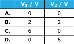
The bulbs are connected to the voltmeter in series. Thus, when one of the bulbs blow, the circuit is now open and no current flows through the circuit.
Thus, by V = RI, V₂ = 0 V.
As the circuit is broken (or open) at L₁, V₁ is now measuring the e.m.f. across the cells (as it is connected to both terminals of the cell).
Thus V₁ = 6 V.
Three identical lamps are connected to a cell as shown below.

Which pair of equations is correct for this circuit?

Ans: C
The identical cell is used in each of the circuits shown below.

The current is the same in each case. What is the resistance of R?
Same current means that the total resistance is the same, given same cell is used.
3 + 2 = 1 + R
R = 4 Ω
What is the effective resistance of the circuit shown below?
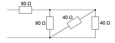
The top \(\text{80 Ω}\) resistor is in series with the other three resistors in parallel.
Let \(R_{eff}\) be effective resistance of the parallel arrangement.
\(\displaystyle{\frac{1}{R_{eff}} = \frac{1}{80} + \frac {1}{40} + \frac {1}{40} = \frac {1}{16}}\\
R_{eff} = 16 Ω\)
Thus, total resistance \(= 80 + 16 = 96 \,Ω\)