Electromagnetism
In this article we will learn about:
- Magnetic effect of a current work
- How to draw magnetic field patterns caused by currents in straight wires and solenoids.
- Observe and state the effect of changing the magnitude or direction of a current on the magnetic field.
- Describe how the magnetic effect of a current in an electromagnet is applied in a circuit breaker.
- The Motor Effect – Force due to Magnetic field and Current Interactions
- Turning effect on a Current-carrying coil in a magnetic field.
Magnetic effect of a Current
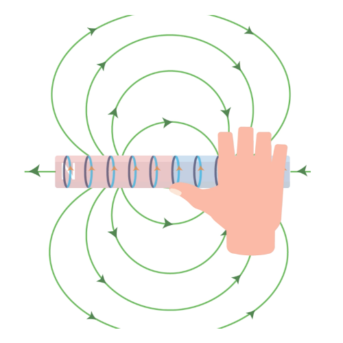
Image Credit: Geniebook source
The above diagram shows a current-carrying conductor with blue turns being electrical dipoles. As these spinning electrons pass through the conductor they generate a magnetic field around the conductor whose magnetic field lines are demonstrated using the green curved lines. These magnetic field lines have a particular direction which depends on the direction of the flow of current. The direction of the magnetic field produced can be determined using the Right-Hand Grip rule.
The above setup where in a current-carrying wire is wound around a soft iron core is called a Solenoid and the entire setup acts as an Electromagnet.
The magnetic field pattern of a solenoid resembles that of a bar magnet. The solenoid has 2 magnetic poles and can be used as an Electromagnet.
Question 1:
Which of the following will NOT increase the magnetic field strength of a solenoid?
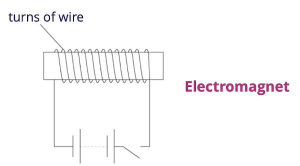
Image Credit: Geniebook source
- Increase the current flowing through the solenoid.
- Increase the e.m.f. of the cells connected to the solenoid.
- Decrease the number of turns per unit length of the solenoid.
- Placing a soft iron core within the solenoid.
Solution:
(C) Decrease the number of turns per unit length of the solenoid.
Explanation:
Decreasing the number of turns per unit length will decrease the magnetic field strength of a solenoid and not increase it. Since there are fewer turns there will be a lesser number of electrons spinning and hence a lesser number of electrons that align resulting in a weaker magnetic field.
A soft iron core will concentrate the magnetic field lines around the solenoid and hence the magnetic field will get stronger.
How was electromagnetism discovered?
The magnetic effect of electric current was discovered through Oersted’s Experiment which was performed in 1820 by a Danish physicist, Hans Christian Oersted.
Oersted’s Experiment
The experimental setup was done as shown in the picture below. When a current is allowed to pass through a wire which is kept in the vicinity of a Magnetic compass, following observations were made:
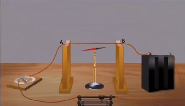
Image Credit: youtube.com
- When the switch is OFF, the compass aligns itself naturally with the earth’s magnetic field and there is no change in its position.
- When the switch is ON and current is allowed to pass through the wire, a deflection is observed in the magnetic field in the direction away from the natural position of the compass. The extent of this deflection would vary as the magnitude of the current would change.
Later, Hans Christian Oersted inferred from the experiment that there must be some form of magnetic field that would cause the magnet to be displaced from its natural position. Through further experimentation, it was observed that the current flowing in the wire was responsible for this magnetic field to be produced.
Question 2:
In which orientation is the compass needle lying when there is no current passing through the wire AB?
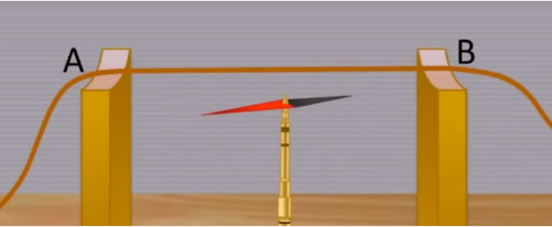
Image Credit: youtube.com
- Along wire AB
- Perpendicular to wire AB
- In the N-S direction of Earth's magnetic field.
- In any random direction.
Solution:
(C) In the N-S direction of Earth's magnetic field.
Explanation:
The compass needle will lie in the direction parallel to the N-S Direction of the Earth’s magnetic field due to the lack of an external magnetic field.
Question 3:
What happens to the compass needle when a current flows in wire AB (placed above the compass needle) as shown?
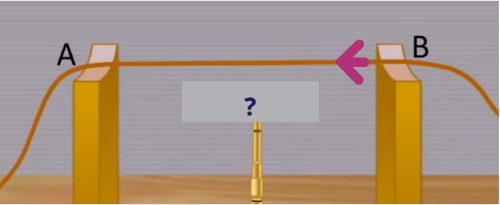
Image Credit: youtube.com
- The compass needle aligns itself with wire AB.
- The compass needle deflects away from the initial earth's N-S orientation.
- The compass needle first deflects away, then returns to the earth's N-S orientation
- No deflection is observed.
Solution:
(B) The compass needle deflects away from the initial earth's N-S orientation.
Explanation:
The compass needle deflects away from the initial earth’s N-S orientation due to the influence of the external magnetic field due to the magnetic field of the current flowing through the wire.
Question 4:
What happens when the compass needle is now placed above wire AB and a current flows in the wire?
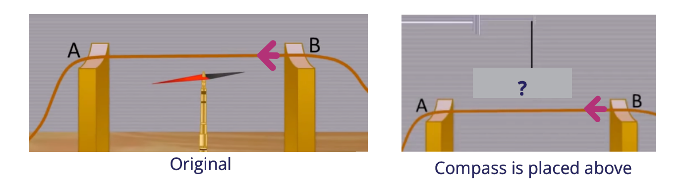
Image Credit: youtube.com
- The compass needle aligns itself with wire AB.
- The compass needle deflects more, in the same direction.
- The compass needle deflects away, in the opposite direction.
- No observable difference in the deflection as before.
Solution:
(C) The compass needle deflects away, in the opposite direction.
Explanation:
The compass needle deflects away, in the opposite direction. This is because of the magnetic field lines that are established around the wire when current passes through it. With the help of the Right-Hand Grip rule, the direction of the magnetic field above and below the wire are in complete opposite directions.
Question 5:
What is the effect on the compass needle when, instead of B to A, the current now flows from A to B?
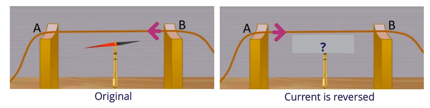
Image Credit: youtube.com
- The compass needle aligns itself with wire AB.
- The compass needle deflects more, in the same direction.
- The compass needle deflects away, in the opposite direction.
- No observable difference in the deflection as before.
Solution:
(C) The compass needle deflects away, in the opposite direction.
Explanation:
By the Right-Hand Grip rule, when the direction of the current changes, the direction of the magnetic field also changes. Thus, the compass needle is also deflected in the opposite direction.
Question 6:
What is the effect on the compass needle when the magnitude of the current is increased?
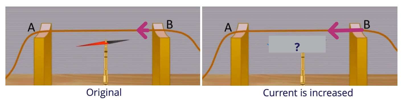
Image Credit: youtube.com
- The compass needle deflects away, in the opposite direction.
- The compass needle deflects more, in the same direction.
- The compass needle deflects more, in the opposite direction.
- No observable difference in the deflection as before (original current magnitude)
Solution:
(B) The compass needle deflects more, in the same direction.
Explanation:
The compass needle will be deflected in the same direction. Since the strength of the current has increased, the strength of the magnetic field produced has also increased while the direction of the field remains the same. Thus, the compass needle will be more “aligned” to the produced magnetic field and deflected more.
Question 7:
Which 2 set-up will produce the same effect on the compass needle?
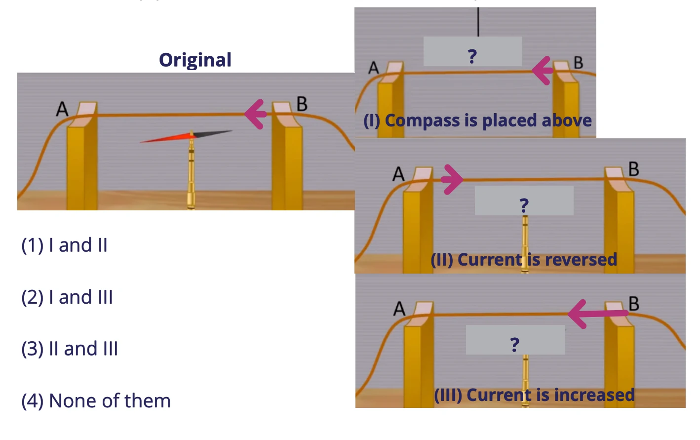
Image Credit: youtube.com
Solution:
(2) I and III
Explanation:
The first and the second setups produce the same effect on the compass as they have been discussed in the previous questions individually.
Magnetic Field Pattern - Straight Wire
From Oersted’s Experiment,
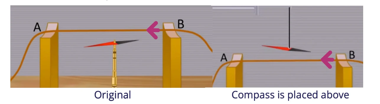
Image Credit: youtube.com
It is found that the magnetic field pattern around a straight current-carrying wire is found to be consisting of concentric circles.
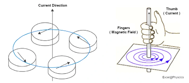
Image Credit: Geniebook source - excelatphysics.com
The directions of both the current and magnetic field can be once again determined by the Right-Hand Grip Rule.
The Right-Hand Grip Rule states that when the thumb represents the direction of current in the current-carrying conductors, the curl of the fingers represents the direction of the Magnetic Field produced.
Right - Hand Grip Rule - 2 Ways To Apply It
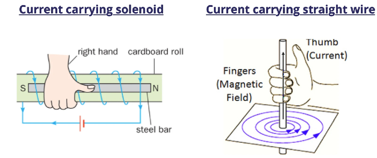
Image Credit: Geniebook source - excelatphysics.com
|
|
|
|
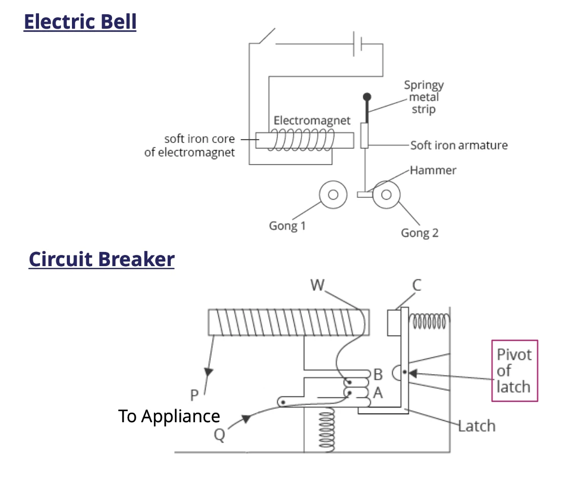
Image Credit: Geniebook.com
Applications of Electromagnet
In the case of an Electric Bell
- Current flows through the solenoid when the bell switch is pressed and the circuit becomes a closed circuit.
- The soft-iron armature is drawn to the electromagnet as it becomes magnetised, and at the same time, the hammer is pulled to strike the gong (gong 1).
- The circuit is open when the person releases his/her hand from the bell switch. The electromagnet loses its magnetization when the electricity stops flowing. As a result, the armature is pulled back by the spring, and the hammer moves right to strike gong 2.
On the other hand, an electromagnet is also used in a circuit breaker using the same principles as that of an electric bell. Let us have a look at it
- An automatic switch, known as a circuit breaker, shuts off the current in a circuit when the current is too high.
- The electromagnet will become more powerful as the current in a circuit increases, which will cause it to attract the soft iron armature.
- As a result, the latch will rotate anticlockwise. This allows the spring to pull the contact A downwards, separating it from B, cutting off the circuit and stopping the flow of current.
- Using the reset button, we can reconnect the circuit. To rejoin the circuit, the contact can be returned to its initial position by pressing the reset button. This will rotate the latch clockwise, opening the contact C from W, push the contact A upwards to touch B and close the circuit again.
Conclusion
In this article, we have learned about the magnetic effect of a current. We saw how to draw magnetic field patterns caused by currents in straight wires and solenoids. We also observed the effect of changing the magnitude or direction of current on the magnetic field.
We also looked at some applications of the magnetic effect of a current.
| Continue Learning | |
|---|---|
| Electromagnetic Spectrum | Sound |
| Static Electricity | D.C. Circuits |
| Electromagnetic Induction | Electromagnetism |
| Magnetism | Current Electricity |
| Practical Electricity | |
Test Yourself
Four compasses are placed around a straight current carrying wire as shown. What can be deduced from the orientations of the needle of the 4 compasses?
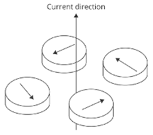
A: Compass needles put close together will influence each other to all point in a circle.
B: Compass needles are affected by the circular electric field in the wire.
C: Compass needles are affected by the circular magnetic field produced by the current in the straight wire.
D: Compass needles will all go around a wire.
A current in a straight wire will always produce a circular magnetic field around it. Compass needles will align themselves along the magnetic field lines.
Ans: (C) Compass needles are affected by the circular magnetic field produced by the current in the straight wire.
An upwards force acts on a piece of wire which carries current in it.
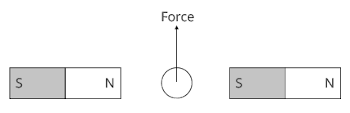
What is the direction of the current in the wire?
Using Fleming’s Left Hand Rule, the current should be moving out of the plane of the paper to achieve an upwards force.
Ans: (D) Out of the plane of the paper.
A straight wire is carrying a current in a uniform magnetic field as shown.
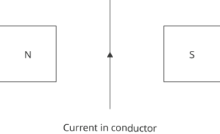
What is the direction of the force acting on the conductor?
The magnetic field lines are directed from the N pole to the S pole.
By Fleming's Left Hand Rule, the force acting on the conductor is into the page.
Ans: (B) into the page
Given that the current flowing through the coils below are equal, which of the following coils produces the strongest electromagnet?
One of the factors that determine the strength of the electromagnet is the number of coils per unit length: the higher the number of coils per unit length, the stronger the electromagnet.
Ans: (B) A 10 cm coil with 100 turns.
Which of the following makes the strongest electromagnet?
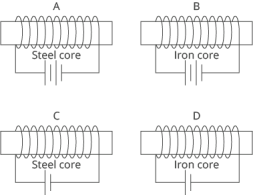
One of the factors that determine the strength of the electromagnet is the magnitude of the current flowing in the solenoid. Having more cells connected in series can increase the voltage across the solenoid and hence increase the current flowing through the solenoid.
Another factor is the material for the core. Iron is a soft magnetic material. It is easier to magnetise than steel.
Ans: (B) Figure B